Why Is the Material Flow Intermittent on My Caterpillar AP555F?
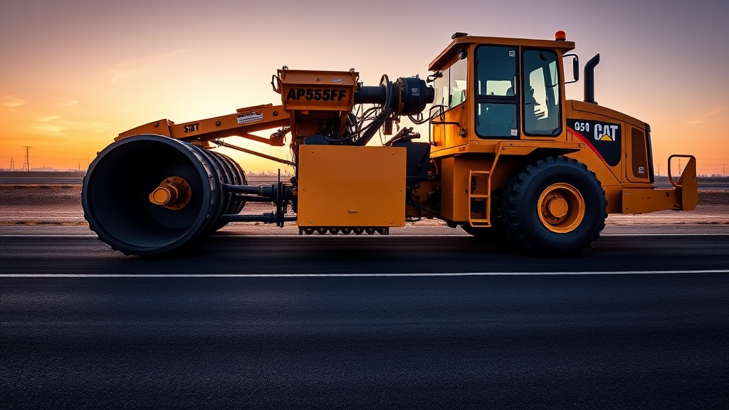
Intermittent material flow is one of the most common complaints from paving crews operating the Caterpillar AP555F. When the mat suddenly thins or stops, it often traces back to a clogged or malfunctioning feed system. The first thing to check is the feed opening — stones or debris can accumulate at the tunnel entrance if the material transport vehicle dumps off-center. If the tunnel is clear, move to the flow sensors and paddle position. The AP555F relies on a pair of mechanical or ultrasonic sensors to regulate the feeder rate. If one paddle sticks due to asphalt buildup or a bent bracket, the system assumes the material level is high and slows the feeder. This creates starvation on that side of the screed.
Operators should also inspect the feeder potentiometer connections. Corrosion or loose wires at the left-to-right transfer junction can cause erratic voltage signals. A quick diagnostic using the digital display’s “Feeder Status” menu will tell you if the left and right sensor voltages match within 0.1 V DC. If not, you likely have a mechanical binding or electrical fault. For deeper electrical diagnostics, see our Caterpillar AP555F Screed Electrical System Troubleshooting Guide.
How Do I Fix Conveyor Chain Slippage on the AP555F?
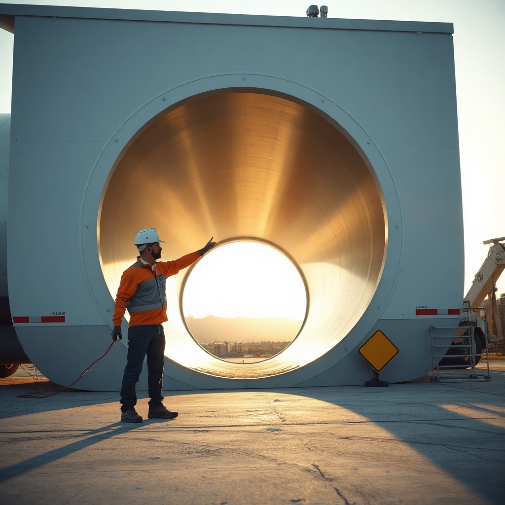
Conveyor chain slippage presents as a loud clattering under the truck hopper and uneven material delivery to the augers. This issue usually stems from one of three causes: worn sprocket teeth, improper chain tension, or a seized roller bearing. The AP555F uses two separate conveyor chains — one for each feed tunnel — each driven by its own hydraulic motor. To diagnose, raise the hopper and inspect the chain for slack. The manual calls for a free span deflection of 6 to 12 mm at the midpoint with the engine off and the system relieved of hydraulic pressure.
If you find slack beyond 15 mm, adjust the idler bearing take-up assembly on the front of the machine. Turn the adjusting bolts in 5 mm increments on both sides, then rotate the conveyor by hand to check for even tension. For sprocket wear, measure the tooth profile against a new sprocket — hooks or sharp points mean replacement. A seized roller bearing feels hot to the touch after 10 minutes of operation and may show discolouration around the bearing housing. Replacing a seized bearing requires removing the conveyor chain and cleanout pan, which is covered in our hydraulic maintenance essential tips.
What Causes Auger Binding and How Do I Resolve It?
Auger binding manifests as slow or jerky rotation, often with a groaning hydraulic sound. The main culprit is material buildup between the auger flights and the tunnel walls, especially when using a high RAP content mix. If the augers hit the side plates, you’ll see shiny rub marks on the painted surfaces. Other causes include worn auger support bushings or a bent auger shaft. The AP555F augers are split in two sections (left and right) and driven by independent hydraulic motors. A high-pressure spike in one motor circuit — often over 280 bar — signals mechanical resistance.
Start by cleaning the auger tunnel thoroughly. Use a steel scraper to remove hard-packed asphalt from the flight tips and tunnel liner. Next, check the auger support bushings by lifting each auger section with a pry bar; if vertical movement exceeds 3 mm, replace the bushings. For a bent shaft, roll the auger by hand and watch for wobble at the coupling. A bend over 2 mm requires replacement. Finally, verify that the auger motor drain line returns clean oil to the tank — restricted drains cause back pressure that mimics mechanical binding. Compare the AP555F auger design with competitors in our in-depth comparison.
How Do I Calibrate the Material Feed Sensors Correctly?
Improper sensor calibration leads to either a sloppy mat (too much material) or a starved mat (too little). The AP555F typically uses either mechanical paddle sensors or ultrasonic sensors. For paddle sensors, calibration involves setting the start and stop angles. With the engine running and feeder engaged, manually push the paddle to the full stop position (approximately 60 degrees from vertical). Note the voltage on the display — it should read between 4.5 and 5.0 V DC. Then let the paddle drop to the start position (about 15 degrees) — this should read 0.5 to 1.0 V DC. If out of range, loosen the paddle arm and adjust the magnet position relative to the sensor board.
For ultrasonic sensors, ensure the sensor face is clean and unobstructed. Place a flat metal plate exactly 200 mm below the sensor face (simulating the material level). In the calibration menu, select “Teach” for that sensor. The system will record the distance as the “full” level. Then lower the plate to 600 mm and teach the “empty” level. Always recheck on a real material test pass. A common error is teaching a full level with the plate too close — the system will then overfeed. For wear trigger points from incorrect feeding, see our practical wear indicators guide.
Why Does the Feed System Overload the Engine?
When the feed system demands more power than the engine can deliver, you’ll notice a drop in engine RPM (from 2200 to below 1900 under load), black exhaust smoke, and potentially the auto-deceleration feature disabling. This overload usually stems from one of three issues: a stuck flow control valve in the feeder pump, a failed pressure compensator, or excessive friction in the conveyors and augers. The AP555F uses a load-sensing hydraulic system — the pump adjusts flow based on demand. If the compensator spool sticks, the pump goes to full stroke regardless of need, hogging horsepower.
To diagnose, monitor hydraulic pressure at the feeder pump test port while running the conveyors in idle. Normal standby pressure is 20 to 25 bar. If you see over 30 bar at idle, the compensator is faulty. Clean the compensator spool and bore with brake cleaner; if scoring is present, replace the spool and sleeve. For friction-related overload, check the conveyor chain tension again (as above) and the auger well cleanliness. Also inspect the cleanout pan drag — a jammed pan increases rolling resistance dramatically. Engine-specific maintenance to manage load is covered in our comprehensive guide.
What Is the Correct Grease and Lubrication Procedure for Feed Bearings?
Neglecting lubrication on the AP555F feed system bearings leads to premature wear and costly downtime. The main lubrication points are the auger support bearings (two per side), the conveyor shaft bearings (two per tunnel), and the paddle sensor pivots. Caterpillar recommends a lithium complex grease with NLGI grade 2 and EP additives. Grease intervals depend on material type but a good rule for standard hot mix asphalt is every 8 operating hours. For high-abrasion or high-RAP mixes, reduce the interval to every 4 hours.
Use a hand grease gun and pump slowly until fresh grease purges from the seal — never use an air-powered gun as it can blow out the seal. Over-greasing can be as harmful as under-greasing, causing seal failure and contamination. After greasing, run the feed system for two minutes to distribute the lubricant evenly. Keep a logbook of grease usage; a sudden increase indicate a worn bearing that is consuming more grease. Below is a severity guide for common feed system problems.
| Symptom | Likely Cause | Severity | Repair Cost (GBP) |
|---|---|---|---|
| Intermittent feed on one side | Stuck paddle sensor | Moderate | £180 – £350 |
| Conveyor chain clatter | Loose chain tension | Low | £50 – £150 |
| Auger binding with noise | Worn auger bushings | High | £600 – £1,200 |
| Engine overloading during feed | Stuck flow compensator | Critical | £400 – £900 |
| Grease purging black | Bearing contamination | High | £250 – £500 |
| Screed mat tearing | Auger over/under feed | Moderate | £100 – £400 |
What Owners Say About the AP555F Feed System
Experienced AP555F owners and operators share a common refrain: the material feed system is the heart of the machine, and it rewards those who stay on top of maintenance. “I run 12-hour shifts on motorway spec jobs,” says Paul, a Durham-based paving contractor. “The AP555F feed never lets me down as long as I clean the auger well every night and grease the bearings every morning. If I skip a day, I pay for it with a rough mat.”
Another operator, Simon from Bristol Asphalt Services, notes that the paddle sensors can be finicky with recycled mixes. “Use high RAP above 50%, and the paddles get sticky. I switched to ultrasonic after a season of constant recalibration — best investment I made.” Owners also praise the load-sensing system for fuel economy, but warn that ignoring a sticky flow control valve can lead to a £900+ pump replacement. “I saw one guy burn out his main feeder pump in under a week because he thought the engine was just tired. It was the compensator,” relates a Caterpillar technician. Business owners who have followed our screed plate replacement procedure report that matching feed tuning to new screed plates cuts material waste by up to 12%.
Frequently Asked Questions
1. Can I run the AP555F feed system with one side disabled?
Yes, but only for emergency moves or loading onto a trailer. Operating with one feed tunnel disabled creates uneven mat depth and excessive wear on the working side. Do not exceed 30 minutes of paving in this mode.
2. How often should I replace the feed tunnel liners?
Replace when wear exceeds 50% of the original thickness, typically every 600-800 paving hours. Use ultrasonic thickness gauge to measure. Thinner liners cause auger deflection and poor material flow.
3. Why does my left feed always run faster than the right?
This is often due to a misaligned truck dump point. If the truck dumps 100 mm off-centre, the left tunnel gets more material, causing the left sensor to pause less and the feeder to speed up. Retrain the truck driver to centre the dump.
4. What is the correct hydraulic oil for the feed system?
Caterpillar recommends Cat HYDO 10W (or equivalent API CI-4 10W-30). Avoid multi-viscosity oils above 10W-30 as they thicken in cold weather and slow the feeder response. Always use a filter with a 10-micron rating.
5. How do I test a feed system potentiometer?
Disconnect the potentiometer from the controller. Measure resistance between the centre pin and each outer pin while moving the actuator arm. The resistance should change smoothly from 0 to 10,000 ohms. Any dead spots indicate replacement is needed.
6. Can I retrofit ultrasonic sensors to an older AP555F?
Yes, Caterpillar offers a retrofit kit (part number 3E-8655) that includes wiring harness and mounting brackets. Expect a cost around £1,200 to £1,600 including labour. The upgrade improves reliability with high-RAP and warm-mix asphalt.